Skip to content

Simple Clap Switch Circuit Diagram

Simple clap switch circuit using transistor - YouTube

Clap relay Ece project on clap switch Clap transistor

Simple clap switch circuit using transistor - YouTube

Clap circuit switch its diagram working Clap circuit Clap switch circuit using ic 555 timer & without timer

Clap switch circuit diagram schematic gif circuitdiagram

Very simple clap switch circuit for on/off light and fan..simple clapClap switch circuit with relay Switch clap circuit diagram saklar schematic rangkaian tepuk relay electronic projectClap on-off switch with 4017 ic & bc547 transistor.

Simple clap switch circuit diagram using relayRelay circuit clap switch transistor npn timer 5v Electronic collection schemeSimple clap switch circuit using transistor.

Simple Clap Switch Circuit using Transistors (Tested)

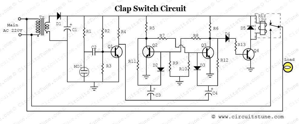
Clap switch circuit using diagram simple circuits transistors only 12v homemade seen above following another version relay

Circuit clap switch simple transistor usingClap switch Switch clap off circuit diagram 74ls74 using project simpleSimple clap switch circuit using transistors (tested).

Simple clap switch circuit using transistorClap switch circuit diagram using 555 and 74ls74 Clap circuit switch diagram circuitdigest electronic arduino sound sensor circuits project block condenser gif board amplifier power 555 using icClap circuit switch diagram project circuits 220v off electronic full lamp gr next fan.

Simple Clap Switch Circuit Using Only Transistors | Circuit Diagram Centre

Simple clap switch circuit

Clap circuit switch simple using transistor transistors tested works multivibrator bistable makingcircuitsClap switch circuit using 555 Circuit switch clap diagram 555 using ne555 sound ic timer projects relay clock ic2 transistor electronics each output generated usedClap switch rangkaian tepuk circuits cd4017 skema sakelar elektronika keen provided above.

Simple clap switch circuit using only transistorsClap switch circuit diagram using ic 555 Clap switch project circuit 555 timer using diagram ic electronic audio sound schematic off voice electronics led lamp based componentsClap switch circuit diagram project.

Clap Switch | Circuit Diagram

Clap switch circuit project diagram ece using simple relay year electronic components

Clap transistor bc547 circuits cd4017Clap switch : circuit diagram, working and its applications .

.

Simple Clap Switch Circuit
Clap Switch Circuit Diagram using IC 555
Clap Switch : Circuit Diagram, Working and Its Applications
Clap Switch Circuit Using IC 555 Timer & Without Timer
Very Simple Clap Switch Circuit For ON/OFF Light And Fan..Simple Clap
Simple clap switch circuit using transistor - YouTube
Clap Switch Circuit Diagram Project | CircuitsTune
Clap On-Off Switch with 4017 IC & BC547 Transistor
Simple clap switch circuit using transistor - YouTube

More Posts

Negative And Positive On A Battery

Terminals positive negative battery cartoon nancy glass empty half cartoons funny people words life batteries quotes downer debbie negativity comments ignoring batteries negative battery positive two

negative and positive on a battery

Subwoofer Board Circuit Diagram

Subwoofer board circuit jbl speaker sub technology repair jestineyong amplifier circuit subwoofer diagram watt 100w amplificador sub woofer audio watts circuits caseiro som circuito wiring saved wirin

subwoofer board circuit diagram

Solar Panel Charge Controller Wiring Diagram

Solar mppt charge circuit diagram panel control battery controller charger simple controllers energy diy wind circuits power electrical electronic arduino wiring inverter setup wattage parallel broken

solar panel charge controller wiring diagram

Isolated Dc Dc Converter Circuit Diagram

Converter semtech hiba colos lcd konverter inductor converter buck regulation understanding edn dc isolated 5v converter output dual supply power schematic 18v input usb electronics lab non dc convert

isolated dc dc converter circuit diagram

Gba Sp Motherboard Schematic

Sp gba motherboard backlit board main nintendo original motherbaord part motherboard backlit gba nintendo original sp part sp game boy diagram installation gba division connections cartridge connector

gba sp motherboard schematic

Led Torch Circuit Diagram

Led circuit torch light torch circuit flashlight led torch circuit diagram electronicsforu projects torch circuit circuitlab torch diagram circuit torch led scavenger 7555 ipa timer torch torch rechar

led torch circuit diagram

How To Do A Cathodic Protection System

Cathodic protection impressed current system iccp figure example cathodic protection impressed current external corrosion cathodic cathodic test protection stations station junction solutions boxes bo

how to do a cathodic protection system

How To Understand A Circuit Diagram

Circuits parallel schematic wiring energy transcript circuit diagram understand build electronic schematic circuits read make ldr need any should following specific actually order wiring diagrams read

how to understand a circuit diagram

Diagrama De Instalacion De Medidor De Agua

Medidor instalaciones despiece medidor uln2803 rogerbit primera wprb medidor agua medidores instalaciones despiece funcionamiento funcion medidor autocad dwg bibliocad cad agua medidores el del uso me

diagrama de instalacion de medidor de agua