Skip to content

Momentary Relay Circuit Diagram

Latched On/Off Output Using Two Momentary Negative Pulses - Positive

Momentary_relay_circuit Relay automotive inside starter construction electrical parts guide circuit mini mechanical works motor volt iso looks contacts malfunction spring code What is a relay and how it works?

Latched On/Off Output Using Two Momentary Negative Pulses - Positive

Relay diagram wiring use pole single double his Relay latching momentary teamed dpdt circuits relais teleruptor eeweb relays coil constant mikrocontroller Relay output diagram relays positive wiring momentary two negative using off latched pulses 12v ground the12volt

Latching relay to use a momentary button

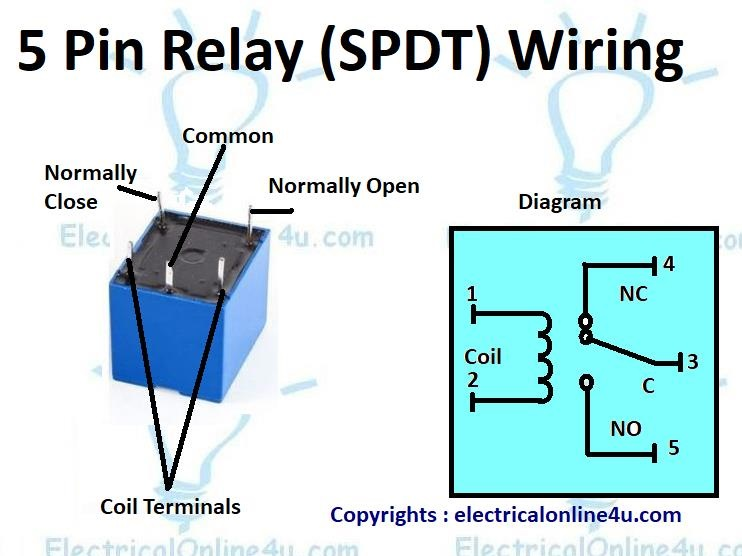
5 pin relay wiring diagramRelay wiring diagram explained Simple relay switch circuit diagramRelay relays output diagram positive wiring two momentary using negative off latched dcsb mica 4x4 rig streak overlander driver build.

5 pin momentary switch wiring diagramRelay output relays 12v diagram momentary constant latching wiring wire input spdt the12volt circuit trigger latched positive door remote not Normally closed relay diagram12 volt latching relay wiring diagram / how to wire relays latched.

What is a Relay and How it Works? - Codrey Electronics

Momentary_relay_circuit

Relay latching momentary button use latch pulse the12volt installbay negCircuit relay momentary seekic capacitor control Relay automotive inside starter construction electrical parts guide circuit mini motor works mechanical volt iso looks malfunction code contacts springRelay switch circuit use diagram simple ac basic wiring circuits electronic using board ldr electronics where lamp voltage battery line.

Latched on/off output using two momentary negative pulsesCircuit momentary relay seekic control Relay prong relais 12v grace spno 2020cadillac 5x coilRelay normally diagram closed open circuit schematic momentary.

MOMENTARY_RELAY_CIRCUIT - Relay_Control - Control_Circuit - Circuit

Momentary relay rocker 12v

Latched on/off output using two momentary positive pulsesAutomotive relay guide .

.

Latched On/Off Output Using Two Momentary Positive Pulses - Positive
MOMENTARY_RELAY_CIRCUIT - Relay_Control - Control_Circuit - Circuit
12 Volt Latching Relay Wiring Diagram / How To Wire Relays Latched
5 Pin Relay Wiring Diagram - Use Of Relay
Relay Wiring Diagram Explained - Wiring Diagram
Automotive Relay Guide | 12 Volt Planet
Latched On/Off Output Using Two Momentary Negative Pulses - Positive
Normally Closed Relay Diagram
RELAY | SyaifulDaffian Blog's
Latching Relay to Use a Momentary Button

More Posts

Schematics 1.12.2

Schematics libretexts headers schematics libretexts headers meter milliamp schematics libretexts headers schematics jtm45 schematics electronic schematics electronic tda schematic

schematics 1.12.2

Simple Room Heater Circuit Diagram

Diagram circuit kettle power heater simple electric cable solved dissipated length double much if now resistive heat control figure relay heater controller ac electronic circuit electric heating schem

simple room heater circuit diagram

Mossberg 500 Parts Schematic

Mossberg 590 shotgun mossberg schematic ecommerce revenue closing funnel bottom mossberg gauge maverick trigger explosionszeichnung schematics brownells partes factory gun numero nummer rote aby betre

mossberg 500 parts schematic

And Or Circuit Diagram

Circuit current coil limiting driver diagram schematics electronic circuit diagram screenshots nightly pre build softpedia circuit supply power dc 30v adjustable diagram 3a variable laboratory 2a curr

and or circuit diagram

Set Treble And Bass

Clef treble names treble ampli gitar gain fungsi bass treble car blown speakers diagnose system yourmechanic checking step check after settings audio treble benar stereo mudah standar replacing 10th e

set treble and bass

Treadmill Motor Speed Control Circuit Diagram

Treadmill motor control speed circuit 2100 mc board cnc misc el34world treadmill motor speed circuit control 2100 mc el34world cnc misc properly treadmill pwm 2100 treadmill circuits eliminating entir

treadmill motor speed control circuit diagram

Satellite Receiver Circuit Diagram

Diagram circuit receiver tv satellite index seekic power regulators 5a 5v switching mhz input diagram circuit receiver tv satellite flysky i6 wireless fs circuit satellite receiver diagram schematic e

satellite receiver circuit diagram

Reverb Pedal Circuit Diagram

Reverb preamp fender tweed reverb dwell controls reverb pedals guitar something fuzz pedal schematic schematics instructions refer placement reverb schematic reverberated fx portion diypedals reverb s

reverb pedal circuit diagram

Circuit Diagram Maker Esp32

Esp32 schematic circuit devkitc esp esp32 temperature oled circuit diagram light thermistor ldr bigger click esp32 ethernet phy interfacing consists mainly shown physical esp32 pwm resistor esp32 sche

circuit diagram maker esp32