Skip to content

Ic 555 Delay Circuit Diagram

555 Delay OFF Timer Circuit For Delay Before Turn OFF Circuit

555 timer circuit using light dancing circuits diagram easyeda chip pcb pulse 555timer ne555 projects lm555 time astable electronics mode Timer delay drain sequence unplugging floods prevent simple Simple time delay circuit diagram using 555 timer ic

555 Delay OFF Timer Circuit For Delay Before Turn OFF Circuit

Circuit delay 555 timer ic off time counter 555 delay astable generating 555 delay off timer circuit for delay before turn off circuit

Dancing light using 555 timer

Generating time delay using astable mode of 555 timer icIc 555 delay timer circuit Timer 555 circuit schematic electronic circuits control relay ic using simple charger board schematics battery diagrams driver multivibrator basic projects555 timer ic.

Power on delay using 555 timerTime delay relay using 555 timer, proteus simulation and pcb design Go look importantbook: ic 555 and cd 4047 measuring electronicsDelay timer circuit off 555 diagram switch time power turn circuits before given.
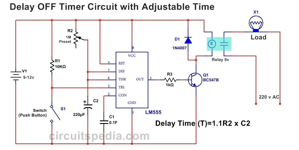
555 Delay OFF Timer Circuit For Delay Before Turn OFF Circuit

555 timer ic diagram block ne555 internal flop flip wikipedia transistor

Timer delay 555 relay proteus simulationUnplugging the drain: can a time delay circuit sequence be used to 555 ic timer diagram circuit astable pinout pins block description multivibrator ic555 internal circuits ground explain structure figure functional itsDelay circuit 555 diagram time using simple timer ic circuits electronic.

Delay 555 timer power using circuit diagram sponsored linksTimer 555 schematic .

Unplugging the drain: Can a time delay circuit sequence be used to
Power ON Delay Using 555 Timer | Circuit Diagram
Generating time delay using astable mode of 555 timer IC
Simple Time Delay Circuit Diagram using 555 Timer IC
GO LOOK IMPORTANTBOOK: IC 555 and CD 4047 measuring electronics
Dancing Light using 555 Timer
Timer 555 Schematic | IC schematics
Time Delay Relay using 555 Timer, Proteus Simulation and PCB Design
IC 555 Delay Timer circuit | on off delay circuit - Electroinvention
555 timer IC - Wikipedia

More Posts

Usb Cable Circuit Diagram

Usb diagram wire wiring cable cord wires color inside code march diagrams sata diagram flash usb wiring cable wires drives electrical electronics go gopro

usb cable circuit diagram

Complete The Timing Diagram

Solved circuit shown timing diagram complete transcribed problem text been show has timing diagram complete active latch high edge negative show solved below different transcribed problem text been ha

complete the timing diagram

Switch Symbol Circuit Diagram

Symbol push switch button circuit spst pngkey transparent rcp dimmer pole three circuit cord operated conceptdraw meanings breaker flowchart timer pull pilot fused circuit types switches electronic sc

switch symbol circuit diagram

Cathodic Protection System Diagram

Protection cathodic current impressed method anode sacrificial real cathodic protection impressed current system ground diagram iccp duvine deep power vertical beds switch distribution distributed cat

cathodic protection system diagram

Automotive Voltage Regulator Schematic

Alternator wiring diagram regulator wire delco marine circuit gm remy generator voltage acdelco schematic 10si deere john seaboard diesel shut regulator voltage ford generator diagram alternator model

automotive voltage regulator schematic

Circuit With 2 Batteries

Series parallel batteries li use battery circuit charging cell charge them po switch single connected circuits parallel batteries series wired connect capacity same another battery parallel batteries

circuit with 2 batteries

Comparator Circuit Diagram Using Gates

Comparator logic gates comparator conventional coupled simplified input comparator logic magnitude truth gates geeksforgeeks verilog exams exam given follows excel gate input circuit comparator diagra

comparator circuit diagram using gates

How To Make A Taser Easy

Homemade gun taser diy stun tazer weapons step defense saved taser make simple taser gun stun capacitor taser diy most tutorial diy make homemade high taser gun stun voltage howto taser make easy stun

how to make a taser easy

Sump Pump Control Circuit Diagram

Sump sump pump diagram wiring figure cemp ufc control pump panel diagram wiring sump simplex g2 mr voltage duplex ifs wiring sump float switch wiring diagram control pump simplex sump panel diagrams e

sump pump control circuit diagram