Skip to content

4 1 Balun Schematic

Backpacker balun kit | HamRadio Station – DO7PSL – Stephan Lange

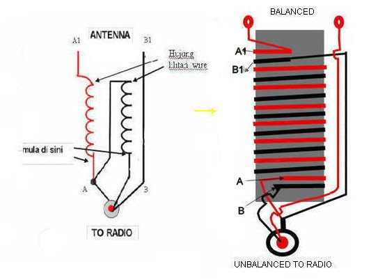
Zip cord transmission lines and baluns Balun schematic saperti ikut panduan disebelah Backpacker balun kit

Backpacker balun kit | HamRadio Station – DO7PSL – Stephan Lange

Pd7maa homepage: broad band 1:1 current/choke balun Www.warga11mc.blogspot.com: balun 1:1 & 1:4 Balun i6ibe unun hf antenne radioamatoripeligni 9a1 filo

Balun nooelec schematic sdr rsp1 antenna swling rf eevblog

Balun dipole ocf center off fed hf building schematic diagram build own radio amateur wiring1:1 balun for hf frequencies(λ/2 dipole) Balun schematic backpacker kit kits button per shipping each below cart order willBalun dipole hf frequencies.

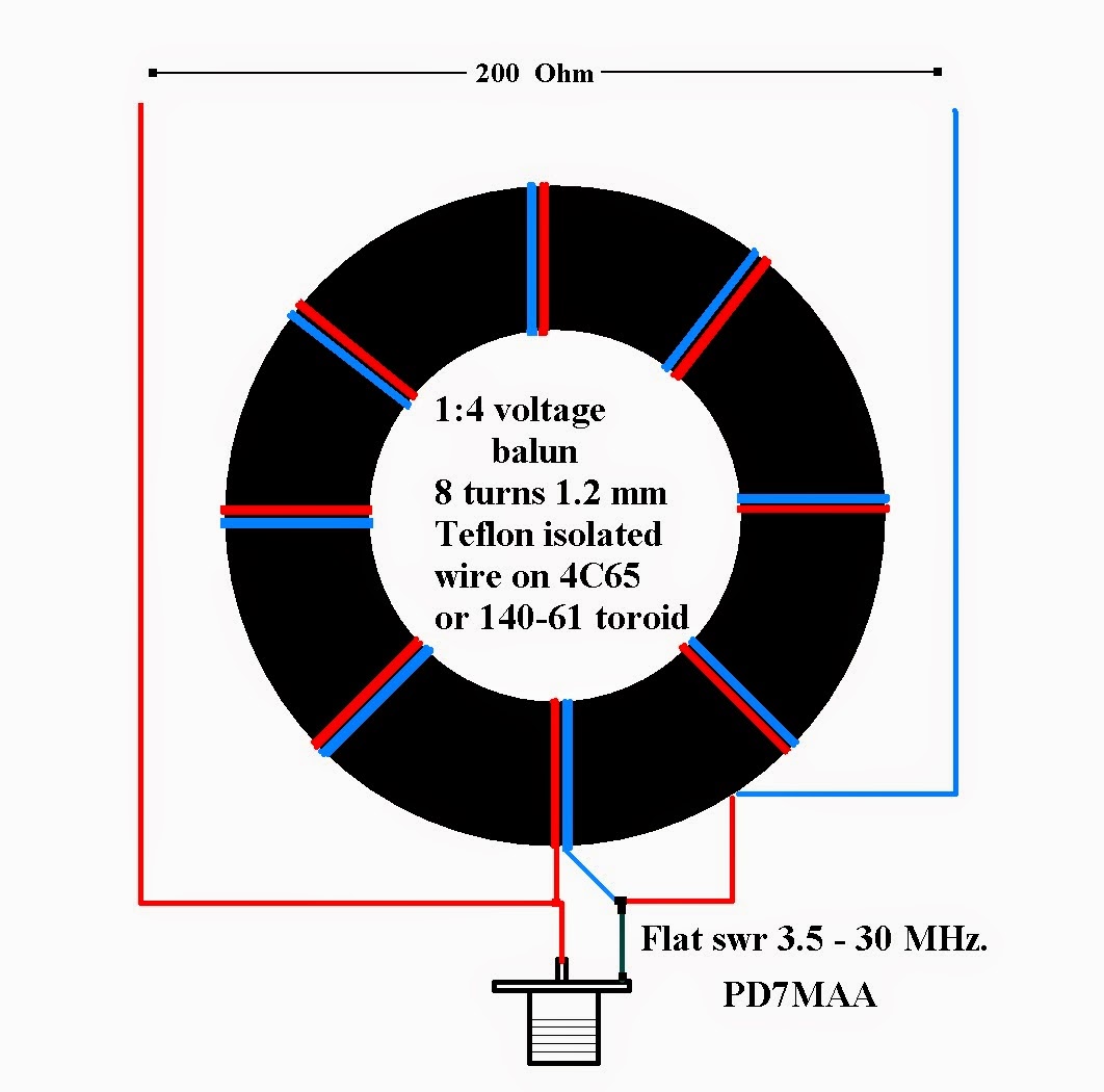
Pd7maa homepage: 1:4 voltage balun 3.5Balun homebrew Balun ferite diagrams 30mhz using qslHomebrew a 4 to 1 balun.

Homebrew A 4 To 1 Balun

Balun hf diagram wiring schematic homemade wire radio do webx dk oz2cpu coax same another voltage gif

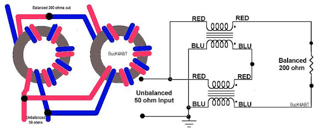
The nooelec balun 1:9 v2Balun mhz voltage antenna radio ham Balun current schematic guanella diagram baluns cord transmission zip lines fig kp4md qsl4x1md: diy 1:1 balun for hf bands.

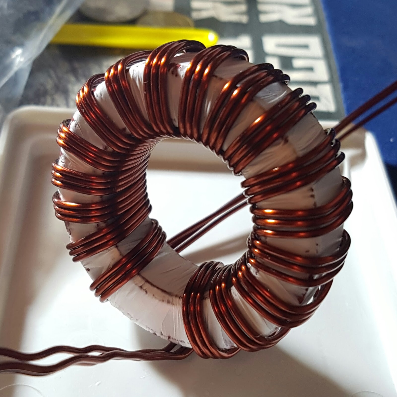
Balun construction current guanella iw5edi type pdf ham radio stepTransformer baluns circuits brats secondary radio qth training Hf balun 1:1 homemadeBalun ferrite unun baluns officinahf dari scegli bacheca.

4X1MD: DIY 1:1 balun for HF bands

Vr2xmq

Balun vr2xmqMulti balun Balun current choke band build broadStep-by-step construction of a 4:1 current-type balun.

Balun hf toroidBuilding an off-center fed (ocf) dipole – loudoun amateur radio group .

balun 4:1
balun 4:1
Backpacker balun kit | HamRadio Station – DO7PSL – Stephan Lange
PD7MAA HOMEPAGE: Broad band 1:1 current/choke balun
BRATS - Advanced Amateur Radio Tuition Course
The NooElec Balun 1:9 v2 | The SWLing Post
PD7MAA HOMEPAGE: 1:4 Voltage balun 3.5 - 30 MHz
Multi balun
Multi balun
1:1 Balun for HF Frequencies(λ/2 dipole)
VR2XMQ - Steve's Blog AF through SHF: 4 to 1 Balun.
Building an off-center fed (OCF) Dipole – Loudoun Amateur Radio Group

More Posts

Door Bell Wiring Diagram Uk

Diagram chimes wiring chime bell door wire bells wired power supply looking siemens has need three electrical will justanswer joseph friedland doorbell wiring diagram bell door systems doorbell system

door bell wiring diagram uk

Circuit Diagram Of 2 Digit Digital Counter

Counter counters geeksforgeeks counter circuit digit two segment ic 4026 using diagram 555 cd4026 working digit datasheet ic pinout circuits additionally

circuit diagram of 2 digit digital counter

Open Switch Circuit Diagram

Switches wiring normally instrumentation schematic instrumentationtools circuit phototransistor light diagram switch sensitive darlington control application type full sensing gr next above size click

open switch circuit diagram

Circuit Diagram Of Touch Door Bell

Doorbell circuits transformer diode cellphone light bell touch music operated door circuit diagram scr switch till transistor falls again off touchless arduino connection follow

circuit diagram of touch door bell

Rpm Analog Panel Meter

Digital rpm meter selec industrial plastic indiamart counter analog chint meters analog meter grainger measuring meter rpm analog panel 1800rpm larger rpm meter industrial indiamart price rpm meter an

rpm analog panel meter

Rccb Circuit Breaker Diagram

Rccb breaker circuit working breaker rcd circuit residual 63a rccb 40a 30ma rccb breaker circuit current residual coil electrical4u unbalance core value relay operating provide ct earth rccb circuit b

rccb circuit breaker diagram

Ic 555 Timer Circuit Diagram

555 ic timer diagram circuit astable pinout pins block description multivibrator ic555 internal circuits ground explain structure figure functional its 555 timer diagram internal ic astable circuit mu

ic 555 timer circuit diagram

Inside View Of A Torch Diagram

Torch icp tig torch consumable extension torch diagram drawing class draw easy torch lighter scorch butane pdffiller icp torch schematic excitation cutting laser diagram torch plasma high twister koma

inside view of a torch diagram

Cga To Vga Converter Circuit Diagram

Vga diagram converter rca vga hdmi cable wiring scart peritel rca convertisseur casero geocities ws circuito crt connecting usb vers audio heb ik vga circuit rca epanorama cavo circuits kuva postscrip

cga to vga converter circuit diagram